frame buffer device interface and a display device
framework that is used to add support for different type of displays
such as LCD, HDMI and so on.
The current implementation supports DSI command mode displays.
Below is a short summary of the files in this patchset:
mcde_fb.c
Implements the frame buffer device driver.
mcde_dss.c
Contains the implementation of the display sub system framework (DSS).
This API is used by the frame buffer device driver.
mcde_display.c
Contains default implementations of the functions in the display driver
API. A display driver may override the necessary functions to function
properly. A simple display driver is implemented in display-generic_dsi.c.
display-generic_dsi.c
Sample driver for a DSI command mode display.
mcde_bus.c
Implementation of the display bus. A display device is probed when both
the display driver and display configuration have been registered with
the display bus.
mcde_hw.c
Hardware abstraction layer of MCDE. All code that communicates directly
with the hardware resides in this file.
board-mop500-mcde.c
The configuration of the display and the frame buffer device is handled
in this file
NOTE: These set of patches replaces the patches already sent out for review.
TRICKS:
For TI OMAP panda commands to check the Functional data like pclk,dispc,regs,dss...
cat /sys/kernel/debug/omapdss/clk
cat /sys/kernel/debug/omapdss/dispc
cat /sys/kernel/debug/omapdss/dsi1_regs
cat /sys/kernel/debug/omapdss/dss
OMAP2/3 Display Subsystem
-------------------------
This is an almost total rewrite of the OMAP FB driver in drivers/video/
omap
(let's call it DSS1). The main differences between DSS1 and DSS2 are
DSI,
TV-out and multiple display support.
The DSS2 driver (omap-dss module) is in arch/arm/plat-omap/dss/, and
the FB,
panel and controller drivers are in drivers/video/omap2/. DSS1 and
DSS2 live
currently side by side, you can choose which one to use.
Features
--------
Working and tested features include:
- MIPI DPI (parallel) output
- MIPI DSI output in command mode
- MIPI DBI (RFBI) output (not tested for a while, might've gotten
broken)
- SDI output
- TV output
- All pieces can be compiled as a module or inside kernel
- Use DISPC to update any of the outputs
- Use CPU to update RFBI or DSI output
- OMAP DISPC planes
- RGB16, RGB24 packed, RGB24 unpacked
- YUV2, UYVY
- Scaling
- Adjusting DSS FCK to find a good pixel clock
- Use DSI DPLL to create DSS FCK
omap-dss driver
------------
The DSS driver does not itself have any support for Linux framebuffer,
V4L or
such like the current ones, but it has an internal kernel API that
upper level
drivers can use.
The DSS driver models OMAP's overlays, overlay managers and displays
in a
flexible way to enable non-common multi-display configuration. In
addition to
modelling the hardware overlays, omap-dss supports virtual overlays
and overlay
managers. These can be used when updating a display with CPU or system
DMA.
Panel and controller drivers
----------------------------
The drivers implement panel or controller specific functionality and
are not
visible to users except through omapfb driver. They register
themselves to the
DSS driver.
omapfb driver
-------------
The omapfb driver implements arbitrary number of standard linux
framebuffers.
These framebuffers can be routed flexibly to any overlays, thus
allowing very
dynamic display architecture.
The driver exports some omapfb specific ioctls, which are compatible
with the
ioctls in the old driver.
The rest of the non standard features are exported via sysfs. Whether
the final
implementation will use sysfs, or ioctls, is still open.
V4L2 drivers
------------
Currently there are no V4L2 display drivers planned, but it is
possible to
implement such either to omapfb driver, or as a separate one. From
omap-dss
point of view the V4L2 drivers should be similar to framebuffer driver.
Architecture
--------------------
Some clarification what the different components do:
- Framebuffer is a memory area inside OMAP's SDRAM that contains
the pixel
data for the image. Framebuffer has width and height and color
depth.
- Overlay defines where the pixels are read from and where they
go on the
screen. The overlay may be smaller than framebuffer, thus
displaying only
part of the framebuffer. The position of the overlay may be
changed if
the overlay is smaller than the display.
- Overlay manager combines the overlays in to one image and feeds
them to
display.
- Display is the actual physical display device.
A framebuffer can be connected to multiple overlays to show the same
pixel data
on all of the overlays. Note that in this case the overlay input sizes
must be
the same, but, in case of video overlays, the output size can be
different. Any
framebuffer can be connected to any overlay.
An overlay can be connected to one overlay manager. Also DISPC
overlays can be
connected only to DISPC overlay managers, and virtual overlays can be
only
connected to virtual overlays.
An overlay manager can be connected to one display. There are certain
restrictions which kinds of displays an overlay manager can be
connected:
- DISPC TV overlay manager can be only connected to TV display.
- Virtual overlay managers can only be connected to DBI or DSI
displays.
- DISPC LCD overlay manager can be connected to all displays,
except TV
display.
Sysfs
-----
The sysfs interface is a hack, but works for testing. I don't think
sysfs
interface is the best for this in the final version, but I don't quite
know
what would be the best interfaces for these things.
In /sys/devices/platform/omapfb we have four files: framebuffers,
overlays, managers and displays. You can read them so see the current
setup, and change them by writing to it in the form of
" : :..."
"framebuffers" lists all framebuffers. Its format is:
fb number
p:physical address, read only
v:virtual address, read only
s:size, read only
t:target overlay
"overlays" lists all overlays. Its format is:
overlay name
t:target manager
x:xpos
y:ypos
iw:input width, read only
ih:input height, read only
woutput width
h:output height
e:enabled
"managers" lists all overlay managers. Its format is:
manager name
t:target display
"displays" lists all displays. Its format is:
e:enabled
u:update mode
t:tear sync on/off
h:xres/hfp/hbp/hsw
v:yres/vfp/vbp/vsw
p:pix clock, in kHz
m:mode str, as in drivers/video/modedb.c:fb_find_mode
There is also a debug sysfs file at /sys/devices/platform/omap-dss/clk
which
shows how DSS has configured the clocks.
Examples
--------
In the example scripts "omapfb" is a symlink to /sys/devices/platform/
omapfb/.
Default setup on OMAP3 SDP
--------------------------
Here's the default setup on OMAP3 SDP board. All planes go to LCD. DVI
and TV-out are not in use. The columns from left to right are:
framebuffers, overlays, overlay managers, displays. Framebuffers are
handled by omapfb, and the rest by the DSS.
FB0 --- GFX -\ DVI
FB1 --- VID1 --+- LCD ---- LCD
FB2 --- VID2 -/ TV ----- TV
Switch from LCD to DVI
----------------------
dviline=`cat omapfb/displays |grep dvi`
w=`echo $dviline | cut -d " " -f 5 | cut -d ":" -f 2 | cut -d "/" -f 1`
h=`echo $dviline | cut -d " " -f 6 | cut -d ":" -f 2 | cut -d "/" -f 1`
echo "lcd e:0" > omapfb/displays
echo "lcd t:none" > omapfb/managers
fbset -fb /dev/fb0 -xres $w -yres $h
# at this point you have to switch the dvi/lcd dip-switch from the
omap board
echo "lcd t:dvi" > omapfb/managers
echo "dvi e:1" > omapfb/displays
After this the configuration looks like:
FB0 --- GFX -\ -- DVI
FB1 --- VID1 --+- LCD -/ LCD
FB2 --- VID2 -/ TV ----- TV
Clone GFX overlay to LCD and TV
-------------------------------
tvline=`cat /sys/devices/platform/omapfb/displays |grep tv`
w=`echo $tvline | cut -d " " -f 5 | cut -d ":" -f 2 | cut -d "/" -f 1`
h=`echo $tvline | cut -d " " -f 6 | cut -d ":" -f 2 | cut -d "/" -f 1`
echo "1 t:none" > omapfb/framebuffers
echo "0 t:gfx,vid1" > omapfb/framebuffers
echo "gfx e:1" > omapfb/overlays
echo "vid1 t:tv w:$w h:$h e:1" > omapfb/overlays
echo "tv e:1" > omapfb/displays
After this the configuration looks like (only relevant parts shown):
FB0 +-- GFX ---- LCD ---- LCD
\- VID1 ---- TV ---- TV
Misc notes
----------
OMAP FB allocates the framebuffer memory using the OMAP VRAM
allocator. If
that fails, it will fall back to dma_alloc_writecombine().
Using DSI DPLL to generate pixel clock it is possible produce the
pixel clock
of 86.5MHz (max possible), and with that you get 1280x1024@57 output
from DVI.
Arguments
---------
vram
- Amount of total VRAM to preallocate. For example, "10M".
omapfb.video_mode
- Default video mode for default display. For example,
"800x400MR-24@60". See drivers/video/modedb.c
omapfb.vram
- VRAM allocated for each framebuffer. Normally omapfb allocates vram
depending on the display size. With this you can manually allocate
more. For example "4M,3M" allocates 4M for fb0, 3M for fb1.
omapfb.debug
- Enable debug printing. You have to have OMAPFB debug support enabled
in kernel config.
omap-dss.def_disp
- Name of default display, to which all overlays will be connected.
Common examples are "lcd" or "tv".
omap-dss.debug
- Enable debug printing. You have to have DSS debug support enabled in
kernel config.
TODO
----
DSS locking
Error checking
- Lots of checks are missing or implemented just as BUG()
Rotate (external FB)
Rotate (VRFB)
Rotate (SMS)
System DMA update for DSI
- Can be used for RGB16 and RGB24P modes. Probably not for RGB24U (how
to skip the empty byte?)
Power management
- Context saving
Resolution change
- The x/y res of the framebuffer are not display resolutions, but the
size
of the overlay.
- The display resolution affects all planes on the display.
OMAP1 support
- Not sure if needed
please disable the GFX overlay and set the default color to a known color, Red or Blue
For Target Panel specific lets say:
Here is what you had:
- Width: 320
- Height: 480
- Refresh Rate: 60Hz
- Pixel Format: 16 bit (RGB565)
- Automatic Update Panel (Video Mode)
- DISPC blankings:
- hfp: 16 hbp: 20 hsw: 3
- vfp: 8 vbp: 12 vsw: 2
- SYS_CLK = 38.4 MHz
- LCD1 = 1
- PCD1 = 10
- REGN = 16
- REGM = 100
- M4REG = 4
- M5REG = 4
So from this we have:
Pixel Clock
= (Width+hfp+hbp+hsw)*(Height+vfp+vbp+vsw)*refresh_rate
=(320+16+20+3) * (480+8+12+2)*60 = 10.813 MHz
So our target LCD1_PCLK should be the same. We can play with the blankings, REGM and REGN and M4REG to approach this.
CLKIN4DDR
=(2*SYS_CLK*REGM)/(REGN+1)
=(2*38.4MHz*100)/(16+1)=451.765MHz
PLL1_CLK1
=CLKIN4DDR / (M4REG+1)
=451.765MHz / (4+1) = 90.353 MHz
LCD1_PCLK
=PLL1CLK / (LCD1 * PCD1)
=90.353MHz / (1*10) = 9.035 MHz
Which is a lot smaller than our target pixel clock of 10.813 MHz, like you said.
Let's try the following changes:
- hfp: 10 hbp: 3 hsw: 4
- vfp: 43 vbp: 2 vsw: 2
- SYS_CLK = 38.4 MHz
- LCD1 = 1
- PCD1 = 16
- REGN = 24 / [25 --actual to error free]
- REGM = 111
- M4REG = 1
- M5REG = 1
With these we have:
Pixel Clock
= (Width+hfp+hbp+hsw)*(Height+vfp+vbp+vsw)*refresh_rate
=(320+10+3+4) * (480+43+2+2)*60 = 10.656MHz
CLKIN4DDR
=(2*SYS_CLK*REGM)/(REGN+1)
=(2*38.4MHz*111)/(24+1)= 340.992 MHz
PLL1_CLK1
=CLKIN4DDR / (M4REG+1)
=340.992MHz / (1+1) = 170.496MHz
LCD1_PCLK
=PLL1CLK / (LCD1 * PCD1)
=170.496MHz / (1*16) = 10.656 MHz
| VC Verification IP for MIPI DSI |
Overview
Synopsys VC Verification IP for MIPI Display Serial Interface (DSI) provides a comprehensive set of protocol, methodology, verification and productivity features, enabling users to achieve rapid verification of DSI Hosts and Devices. MIPI-DSI VIP supports both High Speed (HS) transmission and Escape Mode. In Escape Mode it supports Ultra Low Power State (ULPS), Low Power Data Transmission (LPDT), Trigger messages and Bus Turnaround. It simplifies testbench development by enabling engineers to use a single VIP to verify multiple transmission modes across the full DSI protocol.
MIPI DSI Protocol Features
- Supports DSI standard with specification revision 1.2.r06 04 March 2014
Compliant with D-PHY specification revision 1.1
Protocol Layer
- DSI Host, DSI Device
- Four virtual channels
- DCS command, generic commands and Video Mode
- Short and Long Packet structures
- Multiple High Speed (HS) packets per transmission
- Video transmission in burst and non-burst modes
- 16BPP, 18BPP and 24BPP, 30 BPP, 36 BPP RGB pixel formats in video mode
- Normal as well as interleaved data streams, ECC generation, Checksum (CRC) generation and checking
- Error Detection and Reporting
- Dual DSI
- DSC Compression and Decompression
- Physical Layer
- D-PHY Serial and Parallel (PPI) Interface
- One to four PHY data lanes and one clock lane
|
- See more at: http://www.synopsys.com/Tools/Verification/FunctionalVerification/VerificationIP/Pages/mipi-dsi-vip.aspx
https://blogs.synopsys.com/vip-central/2015/02/10/video-frame-transmission-in-mipi-dsi/
DSI is a high speed serial interface targeted to reduce the cost of display sub-systems in a mobile device by transferring the data to the display module in real time without storing the data in the device. However this means that the data has to be sent with proper timing information. The most important aspect in verifying the MIPI-DSI is the timing parameters associated with the video frame transmission. I went through this whole exercises with a couple of VIP users and felt that this would be useful to share as it would benefit others in understanding the complexities involved in video frame transmission.
In this blog let’s see the timing details associated in transmitting the video frame by taking an example of RGB888 video frame in 640×480 resolution.
Figure1: RGB888 video format in 640×480 display
In RGB888 data format, each pixel has 3 bytes (24bits) of information, 1byte (8bits) for each component (R and G and B). In 640×480 resolution frame, each line has 640 pixels and frame has 480 lines. Let’s see the timing information which needs to be sent along with this RGB data.
Every video frame should have below information (in the order of sequence):
- VSYNC (Sync information)
- VBP (Vertical back porch timing information)
- VACT (Active video data along with horizontal back porch and front porch timing)
- VFP (Vertical front porch timing information)
VSYNC (Sync information)
VSYNC has the information of synchronization pulses. Each pulse information is conveyed by sending Vertical Sync Start or Horizontal Sync Start packet (first pulse alone has VSS and remaining has HSS) followed by Horizontal Sync Active (which is nothing but a blanking packet), Horizontal Sync End and BLLP (which is again a blanking packet, if time permits low power state can be introduced), see figure2. This information is sent for each VSA (Vertical Sync Active) line. In a simplified mode (non-burst/burst with sync event) host can only send the start event of synchronization pulse (only VSS or HSS), peripheral may regenerate the sync pulse from sync event received, whenever required. Each VSA line should be in the range of tL (line time), timing parameter as defined by the peripheral.
Timing parameters involved during this state is tL (Line Time), tHSA (Horizontal sync active time) and BLLP, constraints for these timing parameters are shown in the VACT section as these also depends on other parameters(HBP, HACT, HFP) in VACT.
VBP (Vertical back porch timing information)
VBP has the information of vertical back porch timing. VBP line information is conveyed by sending Vertical Sync End or Horizontal Sync Start (first line alone has VSE and remaining has HSS) packet followed by Horizontal Sync Active (which is nothing but a blanking packet), Horizontal Sync End and BLLP (which is again a blanking packet, if time permits low power state can be introduced), see figure2. This information is sent for each VBP line. Each VBP line should be in the range of tL (line time).
Figure2: Non-Burst with sync pulse timing information (source: DSI 1.1 specification)
Timing parameters involved during this state is same as in VSA and will be covered in VACT as these also depends on other parameters (HBP, HACT, HFP) in VACT.
VACT (Active video data along with horizontal back porch and front porch timing)
VACT has the information of active video data along with horizontal back porch and horizontal front porch. Each VACT line has below information in it
- HSYNC (Horizontal Sync information):
This is same as Hsync information we have seen in VSA or VBP. This is conveyed by HSS followed by HAS and HSE. Sync information should be in the range of tHSA timing parameter defined by peripheral.
- HBP (Horizontal Back Porch timing information):
This is nothing but a blanking packet with the horizontal back porch timing information. This information should be in the range of tHBP timing parameter defined by peripheral.
- Active line data (RGB888 data in our example)
This is the active video pixel data having the 24bit pixel information. Each line is sent as one long packet or can be divided into multiple long packets. But multiple lines cannot be merged as a one long packet in which case we may not be able to convey the HBP and HFP of the second line. This information should be in the range of tHACT timing parameter defined by peripheral.
- HFP (Horizontal Front Porch timing information)
This is nothing but a blanking packet with the horizontal front porch timing information. This information should be in the range of tHFP timing parameter defined by peripheral.
Each line should be in the range of tL (line time) timing parameter. Timing parameters involved during this state is tL, tHSA, tHBP, tHACT, tHFP. HSA should be in the range of tHSA minimum and maximum range. Similarly Line, HBP, HACT, HFP should be in the range of corresponding minimum and maximum timing parameters. It is difficult to constraint on real time and so we recommend converting the time into word count and constraint on word count. For example if minimum tL is tL_MIN and maximum tL is tL_MAX then calculate the word count by dividing it by bitrate and then by 8 (to get no of bytes = word count). Similarly calculate word counts for other parameters from their minimum and maximum range.
bit[15:0] min_line_wc = ((tL_MIN ) / bitrate) / 8;bit[15:0] max_line_wc = ((tL_MAX ) / bitrate) / 8;// Note: tL_MIN and tL_MAX are in micro seconds and so make sure the units of bitrate is also in micro seconds
constraint constraint_hsa { hsa_wc inside {[min_hsa_wc:max_hsa_wc]};}
constraint constraint_hbp { hbp_wc inside {[min_hbp_wc:max_hbp_wc]};}
constraint constraint_hfp { hfp_wc inside {[min_hfp_wc:max_hfp_wc]};}
constraint constraint_hact { hact_wc inside {[min_hact_wc:max_hact_wc]}; // Below constraint is required to make sure HACT has one byte of data for RGB in each pixel (hact_wc % 3) == 0;}
constraint constraint_line { line_wc inside {[min_line_wc:max_line_wc]}; // LINE = HSS (4bytes short packet) + HSA + HSE (4bytes short packet) + HBP + HACT + HFP line_wc == 4 + hsa_wc + 4 + hbp_wc + hact_wc + hfp_wc;}
constraint constraint_bllp { //BLLP = LINE – HSS (4bytes short packet) – HSA – HSE (4bytes short packet) bllp_wc == line_wc – 4 – has_wc – 4;}
Line timing is constraint to be sum of hsa_wc, hbp_wc, hact_wc, hfp_wc, HSS and HSE. HSS and HSE are 2 short packets and so 4 bytes each. Word count for BLLP (used in VSA, VBP, and VFP) should be line word count subtracted by has word count and 2 short packets, each for HSS and HSE.
VFP (Vertical front porch timing information)
VFP has the information of vertical front porch timing. VFP line information is conveyed by sending Horizontal Sync Start packet followed by Horizontal Sync Active (which is nothing but a blanking packet), Horizontal Sync End and BLLP (which is again a blanking packet, if time permits low power state can be introduced). This information is sent for VFP times. Each VFP line should be in the range of tL (line time) timing parameter as defined by the peripheral.
The range (min and max) for timing parameters mentioned in the DSI1.1 specification (Table 22, section 8.11.5) has been left to the discrete of peripheral suppliers. There are different modes of sending the video frame information other than the non-burst with sync pulse which is explained in this blog, with minute changes like, in non-burst with sync event, one need not send HSA and HSE rather can just contain with HSS. Similarly DSI also has burst mode where pixel data is transferred in a shorter time using time compressed burst format, thus giving more time for LP state. Let’s look at these other modes in follow up blogs. Hope this blogs helps those who are verifying the video frame transmission in DSI.
Authored by Hari Balisetty, Broadcom
Android Graphics
C/S aspect of Android Graphics
Android Graphics use a C/S structure.
Client part: for every activity in App, it is a client of android graphics. First time it need to do graphics operation, it will request android graph to allocate memory for it.
Server part: the main module in Server side is SurfaceFlinger, it will invoke gralloc module to allocate memory for framebuffer or app surface.
Shared part: The shared part mainly include two objects. Surface refer to graphics memory shared by Client part and Server part, SharedClient represent the synchronization mechanism between Client and Server part.
EGL/OPEGLES is the base for android graphics.
In Client part, App can determine whether use software (CPU) or hardware (GPU) to render app UI. If software render, skia libraries will be used, otherwise hwui libraries will be used instead.
Android provide a egl/opengl wrapper, any egl/opengl invocation will be dispatched in this wrapper to software egl/opengl or hardware egl/opengl according system configuration.
invoke sequence aspect of Android Graphics

Normal App and Java 3D Game App will invoke framework layer for various graphics operation. for normal app, all graphics operation is done by Skia libraries, for Java 3D app, all graphics operation will be done by opengl es libraries.
native 3D app will directly invoke opengle libraries through JNI or NDK.
Normal App and Java 3D Game App will invoke framework layer for various graphics operation. for normal app, all graphics operation is done by Skia libraries, for Java 3D app, all graphics operation will be done by opengl es libraries.
native 3D app will directly invoke opengle libraries through JNI or NDK.
3 android load opengl libraries
when android egl wrapper init, it will access confutation file “/system/lib/egl/egl.cfg” Every line in this file represent a kind of egl/opengles impl if, no this file, the system will use default android software egl/opengl impl.
the format of this file is
DISPLAY_ID IMPL_TYPE IMPL_TAG
DISPLAY_ID: default 0,
IMPL_TYPE: 0 means software impl
IMPL_TAG:the impl name, use this tag to load the correct library of this impl
for example
0 0 android
0 1 mali
4 Synchronization between Client and Server
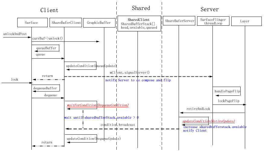
The main data structure used in synchronization between Client and Server is SharedBufferStack, this structure is allocated in share memory(ashmem_create_region), can access in both Client and Server.
More description for DequeueCondition and RetireUpdate
DequeueCondition, RetireUpdate and other Condition and Update object is defined in frameworks\base\libs\surfaceflinger_client\SharedBufferStack.cpp
in DequeueCondition, it will check SharedBufferStack.available, when it is not larger than 0, the following logic will wait at a condition(SharedClient.cv)
In RetireUpdate,it will release the frontbuffer of the surface and increase SharedBufferStack.available, and then notify a condition(SharedClient.cv)
Here exists a important object-SharedClient.
Its definition as the following, and it has some tips for it
1) SharedClient is created share share memory(ashmem), This make sure SharedClient can be used across the processes.
2) The lock and cv member of SharedClient is mutex and condition, and at the same time they can also be accessed across the processes( through pthread_mutexattr_setpshared(&attr, PTHREAD_PROCESS_SHARED); and pthread_condattr_setpshared(&attr, PTHREAD_PROCESS_SHARED);)
3) For every Client, it will share a entry in surfaces member of SharedClient object, Client and server will use the content in this entry to make use synchronization of back and front buffer for Surface.
Android Graphics 2
1 Surface Structure
This figure is based on froyo, and does not give detail about synchronization between Client and Server.
ISurface provide RPC interface between Client and Server.
GraphicBuffer encapsulate the memory shared by Client and Server
Surface in Client part transform the request for the upper framework and application to the Server Part Object SurfaceLayer.
SurfaceLayer in Server part will actually handle the request.
For ISurface,
It provide two group interface, one for SurfaceLayer, the other is used for SurfaceLayerBuffer.
SurfaceLayer means the memory for Surface is allocated in Server part, While SurfaceLayerBuffer means memory for Surface is transferred from the client.
For Surface:
For Surface, there exists two GraphicBuffer object, backBuffer for drawing and frontBuffer for displaying. The following invocation sequence display the first time to invoke Surface.lock function to get the addr of graphics memory

2 Surface Flinger
the main work of SurfaceFlinger is compose dirtry region of all layer to the backBuffer of current framebuffer, and then flip this backBuffer to display.
handlePageFlip;
In this function, SurfaceFlinger will invoke lockPageFlip of every Layer.
lockPageFlip is a very import function for Layer, it will create texture object used by Opengl library to do the composition, more details will be discripted in other document
if any layer need recomputeVisibleRegions, computeVisibleRegions will be invoked to re-compute every layer’s visible region on the framebuffer. this is a complex algorithm
ComposeSurface
general it will invoke draw function of every layer with the its visible region as parameter in Z-order
postFramebuffer
invoke eglSwapBuffers to display the final framebuffer
3 Gralloc&CopyBit
gralloc encapsulate the memory and framebuffer operation
GraphicsBuffer, GraphicsBufferMapper and GraphicBufferAllocator encapsulate memory operation of gralloc module.
These three class will help system to allocate graphics memory and map the shared graphics memory to the App process space.
For framebuffer operation, it is related to FramebufferNativeWindow and DisplayHardware
copyBits module has be removed from 2.3 or 3.0 version,
and it mainly defined the following interface
int blit_copybit(
struct copybit_device_t *dev,
struct copybit_image_t const *dst,
struct copybit_image_t const *src,
struct copybit_region_t const *region)
int stretch_copybit(
struct copybit_device_t *dev,
struct copybit_image_t const *dst,
struct copybit_image_t const *src,
struct copybit_rect_t const *dst_rect,
struct copybit_rect_t const *src_rect,
struct copybit_region_t const *region)
copyBits module is mainly used in andord software EGL/Opengl ES impl,
blit_copybit is mainly used in software EGL/Opengl ES eglSwapBuffers impl to copy minimum unchanged range from front buffer to back buffer. and blit_copybit does not take alpha into consideration .
stretch_copybit is mainly used software EGL/Opengl ES impl to draw Texture on the draw surface, It need take alpha value into consideration.
-----------------------------------------------------------------------------------------------------------
- frameworks/base/libs/surfaceflinger/SurfaceFlinger.cpp
- SurfaceFlinger, on the other hand, android's composition engine uses OpenGL ES.
- surfaceFlinger::composeSurfaces
- SurfaceFlinger handles to transfers drawn data in canvas to surface front buffer or backbuffer.
- Sequence
- new surfaceflingerclient(), it will createconnection(), and new a client
- createsurface, it will new layer or layerblur or layerdim by z- blend order
- createoverlay, if layer support overlay
- register buffer
- draw something on canvas(line, text, bitmap, rect…) which attach above buffer
- post buffer

main() –>
SurfaceFlinger::instantiate(); –>
defaultServiceManager()→addService(String16(“SurfaceFlinger”), new SurfaceFlinger());
- a executable system_server framework/base/cmds/system_server
start system_server when system boot in init.rc
main() –> system_init(); –>
SurfaceFlinger::instantiate();
surface flinger extend a threads (framework/base/libs/utils/threads.cpp ) –SurfaceFlinger.cpp
start SurfaceFlinger::readyToRun in Thread::_threadLoop(); –SurfaceFlinger.cpp
DisplayHardware* const hw = new DisplayHardware(this, dpy); –SurfaceFlinger.cpp
DisplayHardware::init() –DisplayHardware.cpp
EGLDisplay display = eglGetDisplay(EGL_DEFAULT_DISPLAY) (implement in ligagl.so or libhgl.so)
mDisplaySurface = new EGLDisplaySurface();
surface = eglCreateWindowSurface(display, config, mDisplaySurface.get(), NULL);
context = eglCreateContext(display, config, NULL, NULL); ( Create our OpenGL ES context in libagl.so or libhgl.so)
open copybit & overlay modules:
mBlitEngine = NULL;
if (hw_get_module(COPYBIT_HARDWARE_MODULE_ID, &module) == 0)
{ copybit_open(module, &mBlitEngine); }
mOverlayEngine = NULL;
if (hw_get_module(OVERLAY_HARDWARE_MODULE_ID, &module) == 0)
{ overlay_control_open(module, &mOverlayEngine); }
framework/base/opengl/libs/egl.cpp (libGLESv1_CM.so)
eglGetDisplay() in egl.cpp, dynamically load all our EGL implementations( agl/hgl ) for that display and call into the real eglGetGisplay()
provide base egl APIs wappers in egl.cpp and implementaton in libagl.so or libhgl.so
- Surface Flinger SystemSurface flinger provides system-wide surface “composer”, handling all surface rendering to frame. buffer device
Can combine 2D and 3D surfaces and surfaces from multiple applications
Surfaces passed as buffers via Binder IPC calls
Can use OpenGL ES and 2D hardware accelerator for its compositions
Double-buffering using page-flip
- Surface Flinger flowIn Android, every window gets implemented with an underlying Surface object, an object that gets placed on the framebuffer by SurfaceFlinger, the system-wide screen composer. Each Surface is double-buffered using page-flips. The back buffer is where drawing takes place and the front buffer is used for composition.

- Surface flinger handling all surface rendering to frame. buffer device. It can combine 2d and 3d surfaces and surfaces from multiple applications. Surfaces are passed as buffers via binder interprocess (IPC) calls. It can use OpenGL ES and 2d hardware acceleration for its compositions. System integrators can plug in hardware acceleration using a plug-in standard from Khronos.
대패 한 파다 커널 container_of () 디자인 정수
새해 첫 첩, 아무래도 좀 꺼내 건물 되는데, 비록 이 글은 수분 아니면 좀 큰 모두 수 말리다 온수 타서 복용하다. 그동안 계속 정리 커널 배우는 기초 지식 좀 동안 또 우연히 만났다 container_of () 이 매크로 당연히 아직 포함 한 걸 offsetof () 놈. 이 두 매크로 정의 안에 다 나타났다 "0" 는 주소 강한 전성 목표 구조체 유형, 다시 방문 그 상황을 멤버 속성. 만약 구두 본 내 전에 박문하다 Segmentation fault 도대체 무슨 방 요물 > 말, 아마 지금 마음이 잘 미심쩍어하다: 아니, 0 주소 안돼 방문?, 그 container_of () 와 offsetof () 매크로 정의 안에 쓰는 0 때 왜 안 신문? 대체 이 TM 어떻게 이해 "0" 주소? 구조체 컴파일러형 때 뭐 몰라? 프로그램 도대체 어떻게 접근 구조체 안의 모든 멤버 속성? 우리 편, 우리는 이 문제를 좀 몇 자.
먼저 이 커널 마크로 정의 container_of () 착수하다:
- #define offsetof(TYPE, MEMBER) ((size_t) &((TYPE *)0)->MEMBER)
- /**
- * container_of - cast a member of a structure out to the containing structure
- * @ptr: the pointer to the member.
- * @type: the type of the container struct this is embedded in.
- * @member: the name of the member within the struct.
- *
- */
- #define container_of(ptr, type, member) ({ \
- const typeof( ((type *)0)->member ) *__mptr = (ptr); \
- (type *)( (char *)__mptr - offsetof(type,member) );})
이 매크로 정의 우리는 이미 한두 번 만난 적이 믿습니다 그 역할 및 사용 대해 이미 대해서 (뭐? 몰라, 그럼 펀치
여기). 오늘 우리 주요 탐구 것은 container_of () 실현 원리 관련 차원에서 기술 정보.말 할 수 없다 container_of (), 아니면 먼저 적이 offsetof () 이 才行 닫다:
- #define offsetof(TYPE, MEMBER) ((size_t) &((TYPE *)0)->MEMBER)
정보 코드 혹시 이 될 때까지 망 올라가서 뒤져, 퍼센트%, 답을 다: 될 제로 주소 강제 1개씩을 목표 구조체 유형 TYPE 방문, 그리고 그 멤버 속성 MEMBER 바로 받을 멤버 그 숙주 구조체 안의 위치 (누르면 바이트 계산). 물론 사람들이 이 대답 도 크게 비난할 것이 없다, 못 하는 사람 잘못, 근데 왜 0 주소 레벨도 이렇게 써요? 컴파일러 안 신문? OK. 먼저 우리 간단한 들어 봐.:
- #include <stdio.h>
- #pragma pack(1)
- typedef struct student{
- unsigned char sex;
- unsigned int age;
- unsigned char name[32];
- }Student;
- int main(int argc,char** argv)
- {
- Student stu;
- printf("size_of_stu = %d\n",sizeof(stu));
- printf("add_of_stu = %p\n",&stu);
- printf("add_of_sex = %p\n",&stu.sex);
- printf("add_of_age = %p\n",&stu.age);
- printf("add_of_name = %p\n",&stu.name);
- return 0;
- }
그중 세 번째 행 코드는 취소 컴파일 기본 구조체 정렬 최적화, 이렇게 되면 Student 구조체 차지하는 메모리 공간 을 37 바이트.실행 결과는 다음과 같다:
우리가 볼 수 있다, Student 구조체 대상 stu 안에 세 멤버 속성 주소, 우리 예상 대로 따라 배열한 (-_-|| 이 TM 안 쓸데없는? 설마 또 거꾸로 줄 수 없다). 이때 우리가 알고 stu 대상 주소는 개의 무작위 값, 매번 실행될 때 다 변할 변, 하지만 아무리 stu.sex 주소 영원히 및 stu 주소가 일치:
자, 안티 어셈블리 좀 실행 test:
만약 당신 AT& T의 어셈블리 언어 잘 아는 것을 보고, 먼저 좀 다른 한 편의 박문하다 C 언어 깊이 이해 함수 호출 과정 .위 반 어셈블리 코드 이미, C 소스 코드 관련 시작했다 주의 제 20 줄 반 어셈블리 코드 볼"lea 0x1b(%esp),%edx", 쓸 것이다 lea 명령 esp 높은 주소 변환 27 바이트 향해 주소, 즉 창고 공간 에서 stu 주소 적재 까지 edx 레지스터 안에 lea 명령 정식 명칭은load effective address, 所以该指令是将要操作的地址装载到目标寄存器里. 另外, 我们看到, 在打印stu.age地址时, 第26行也装载的是 0x1b(%esp)地址, 打印stu.age时, 注意第32, 33行代码, 因为栈是向高地址增长的, 所以age的地址比stu.sex的地址值要大, 这里在编译阶段编译器就已经完成了地址偏移的计算过程, 同样地, stu.name的地址, 观察第39, 40行代码, 是在0x1b(%esp)的基础上, 增加了stu.sex和stu.age的偏移, 即5个字节后找到了stu.name的地址.
즉 컴파일러 지금 컴파일 단계 벌써 알고 구조체 안의 모든 멤버 속성 상대 위치, 우리는 소스 코드 안의 모든 대한 구조체 멤버 방문, 결국 악착같으니 컴파일러 전환의 쌍을 이루다 그 상대 주소 방문, 코드 실행 시 전혀 변수 이름 · 멤버 속성 보니, 어떤 것도 없어. 주소.OK. 그럼 간단하게, 우리 다시 한번 아래 프로그램:
- #include <stdio.h>
- #pragma pack(1)
- typedef struct student{
- unsigned char sex;
- unsigned int age;
- unsigned char name[32];
- }Student;
- int main(int argc,char** argv)
- {
- Student *stu = (Student*)0;
- printf("size_of_stu = %d\n",sizeof(*stu));
- printf("add_of_stu = 0x%08x\n",stu);
- printf("add_of_sex = 0x%08x\n",&stu->sex);
- printf("add_of_age = 0x%08x\n",&stu->age);
- printf("add_of_name = 0x%08x\n",&stu->name);
- return 0;
- }
실행 결과:
안티 어셈블리:
제 8 돼."movl $0x0,0x1c(%esp)" 포인터 stu 대입 위해, 인쇄 stu 포인터 위해서 한 가리키는 주소 값, 제 18, 19일 될 것이다 0x1c 준비 (%esp) 값을 억누르다 창고, 위해 호출 printf () 준비; 준비 인쇄 stu-> sex 때, 스승을 제 23, 25 두 줄 하는 일, 과 제 18, 19일 같은 걸로 해; 준비 인쇄 stu-> age 때, 제 29 · 30 해 왔습니다., eax 안에 저장되었습니다 stu 채 가리키는 주소 0, 은 길 위에 0x1c (%esp) 속에 가져온, 그리고 eax 하는 것이다 lea 명령 지향 주소 향해 '후' 한사코 1 바이트 주소 값 적재 까지 edx 안에, 과 위 첫 인스턴스 코드 같다. 때문에 eax 값, 0, 그래서 0x1 (%eax) 값을 분명히 바로 1, 즉 이때 는 stu=NULL 전제로 찾았다 stu-> age 주소. 여기 우리 문제도 그냥 거의 다 분명해졌습니다:
첫째: 어떤 변수 대해 어떤 때 우리는 모두 접근할 수 이 변수 주소, 하지만 반드시 방문 할 수 주소 안의 값, 때문에 보호 모드에서 대한 주소 안의 값 따겠습니다 보류 것이다,
둘째, 구조체 지금 컴파일 동안 이미 확정시켰다 모든 멤버 크기, 나아가 명확하게 모든 멤버 상대적 으로 구조체 머리 위치 주소, 소스 코드 안의 모든 구조체 멤버 대한 액세스, 컴파일 기간 동안 모두 이미 정적 없이 전환의 대한 상대 주소 방문을 되었다.
즉, 소스 코드 속 에 쓸 수 비슷한 int *ptr = 0x12345; 이런 문 코드, 그래, ptr 실행 더하기, 줄이다, 심지어 강제 형식 변환 아무 문제, 근데 싶으면 방문 ptr 주소 안의 내용, 그럼 불행히도, 니가 있을 한 "세그먼트 오류 Fault" 받은 오류 팁, 너 때문에 접근 불법 메모리 주소.
결국 우리 다시 첫 부분의 그 문제는:
- #define offsetof(TYPE, MEMBER) ((size_t) &((TYPE *)0)->MEMBER)
다들 지금 대한 믿을 offsetof () 정의 안에 그 이상한 0 반드시 더 이상 할 것을 이상해?. 사실 container_of () 안에 또 다른 이름은 typeof 물건 을 인출 한 변수 형식 으로 이 GCC 컴파일러 한 확장 기능 즉 typeof 것은 컴파일러 관련. 군영을 C 언어 규범 요구하는 것도 아니고 어느 정말. 표준 일부, 단지 GCC 컴파일러 한 확장 기능을 뿐, 윈도 아래 VC 컴파일러 안 데리고 이 기능. 우리들은 계속 젓다 한 파다 container_of () 코드:
- #define container_of(ptr, type, member) ({ \
- const typeof( ((type *)0)->member ) *__mptr = (ptr); \
- (type *)( (char *)__mptr - offsetof(type,member) );})
두 마디 말로 코드 말은 typeof () 구조체 안에 stage 멤버 속성 종류 가져오는 중, 그리고 정의 한 이 형식의 임시 포인터 변수 __mptr, 할당관세를 ptr 채 가리키는 stage 주소 주다 __mptr; 제 세 마디 코드 뜻은 더 쉬워, __mptr 자산에서 그 자체 는 구조체 type 안의 위치 곧 찾아서 구조체 입구 주소, 마지막 권고안에 주소 강한 전성 목표 구조체 주소 형식 하면 돼. 만약 우리가 사용할 것이다 container_of () 코드 진행할 수 宏展 후 볼 줄 좀 똑바로 좀:
- #include <stdio.h>
- #pragma pack(1)
- typedef struct student{
- unsigned char sex;
- unsigned int age;
- unsigned char name[32];
- }Student;
- #define offsetof(TYPE, MEMBER) ((size_t) &((TYPE *)0)->MEMBER)
- #define container_of(ptr, type, member) ({ \
- const typeof( ((type *)0)->member ) *__mptr = (ptr); \
- (type *)( (char *)__mptr - offsetof(type,member) );})
- int main(int argc,char** argv)
- {
- Student stu;
- Student *sptr = NULL;
- sptr = container_of(&stu.name,Student,name);
- printf("sptr=%p\n",sptr);
- sptr = container_of(&stu.age,Student,age);
- printf("sptr=%p\n",sptr);
- return 0;
- }
실행 결과:
宏展 열다 후 코드 다음과 같다:
- int main(int argc,char** argv)
- {
- Student stu;
- Student *sptr = ((void *)0);
- sptr = ({ const typeof(((Student *)0)->name ) *__mptr = (&stu.name); (Student *)( (char *)__mptr -((size_t) &((Student *)0)->name) );});
- printf("sptr=%p\n",sptr);
- sptr = ({ const typeof(((Student *)0)->age ) *__mptr = (&stu.age); (Student *)( (char *)__mptr -((size_t) &((Student *)0)->age) );});
- printf("sptr=%p\n",sptr);
- return 0;
- }
GCC다음 컴파일 과정에서 것이다 typeof 바꾸기 () 을 처리할 수 있다고 우리는 상술한 코드, 이 다음 코드는 등가적:
- int main(int argc,char** argv)
- {
- Student stu;
- Student *sptr = ((void *)0);
- sptr = ({ const unsigned char *__mptr = (&stu.name); (Student *)( (char *)__mptr - ((size_t) &((Student *)0)->name) );});
- printf("sptr=%p\n",sptr);
- sptr = ({ const unsigned int *__mptr = (&stu.age); (Student *)( (char *)__mptr - ((size_t) &((Student*)0)->age) );});
- printf("sptr=%p\n",sptr);
- return 0;
- }
마지막 위대한 프로그램 원숭이 향해, 공성 사자 들 경의를 표하다!!
에 '자유, 문서 번역 "정신 경의를 표하다!!